Motor Side (Device Under Test)
This page covers the motor-side (DUT) hardware, assembly, and control firmware. For the dynamometer side, see Make Your MC-Dyno.
1. Hardware
For a smooth MC-Dyno build…
If you want the most up-to-date DUT-side hardware that is currently used in the majority of the MC-Dyno projects is:
One MCLV-48V-300W Development Board for the Device-Under-Test side
One ACT57BLF02 Motor for the Device-Under-Test side
Required hardware (DUT side)
One MCLV-48V-300W Development Board for the DUT side.
One ACT57BLF02 Motor for the DUT side.
One 3A 24V Power Supply (shared with the dyno side).
Flexible aluminum jaw shaft coupling (if the above suggested motors are used, then 8mm bore should be selected).
Eight M4 x 10 mm hex-socket screws
3D printed brackets, which can be found in the 3Dparts folder (OpenSCAD + STL).
Wood mounting base or 4 (20x20) T-slot aluminum profiles, minimum length 500 mm
For T-slot mounting Eight M5 socket-head cap screws (M5 SHCS) - 16 mm
For T-slot mounting Eight M5 T-slot nuts
Windows PC running Windows 10.
Alternative Hardware (DUT side)
For High Voltage Motor Testing - One MCHV-230V-1.5kW Development Board for the DUT side.
An alternative motor that can be used for the DUT side is the AC300022 - 24V 3-PHASE BRUSHLESS DC MOTOR WITH ENCODER.
2. Assembling the hardware
In this section the steps to build the MC-Dyno motor side (DUT) will be described.
Before starting this guide, navigate to the file section 3Dparts and 3D print the motor mounts for the DUT motor used. For the DUT side, use ACT57BLF_blue_wedge_V1_00.stl. Print one bracket for the DUT motor. There are two bracket sizes available: small for portable demonstrators (blue wedge) and standard size (unified). Before printing, decide the motor brackets versions that matches best your setup. You can also find the openSCAD files for the brackets in there, so if you would like to modify this model to fit a different motor, you’re welcome to do so.
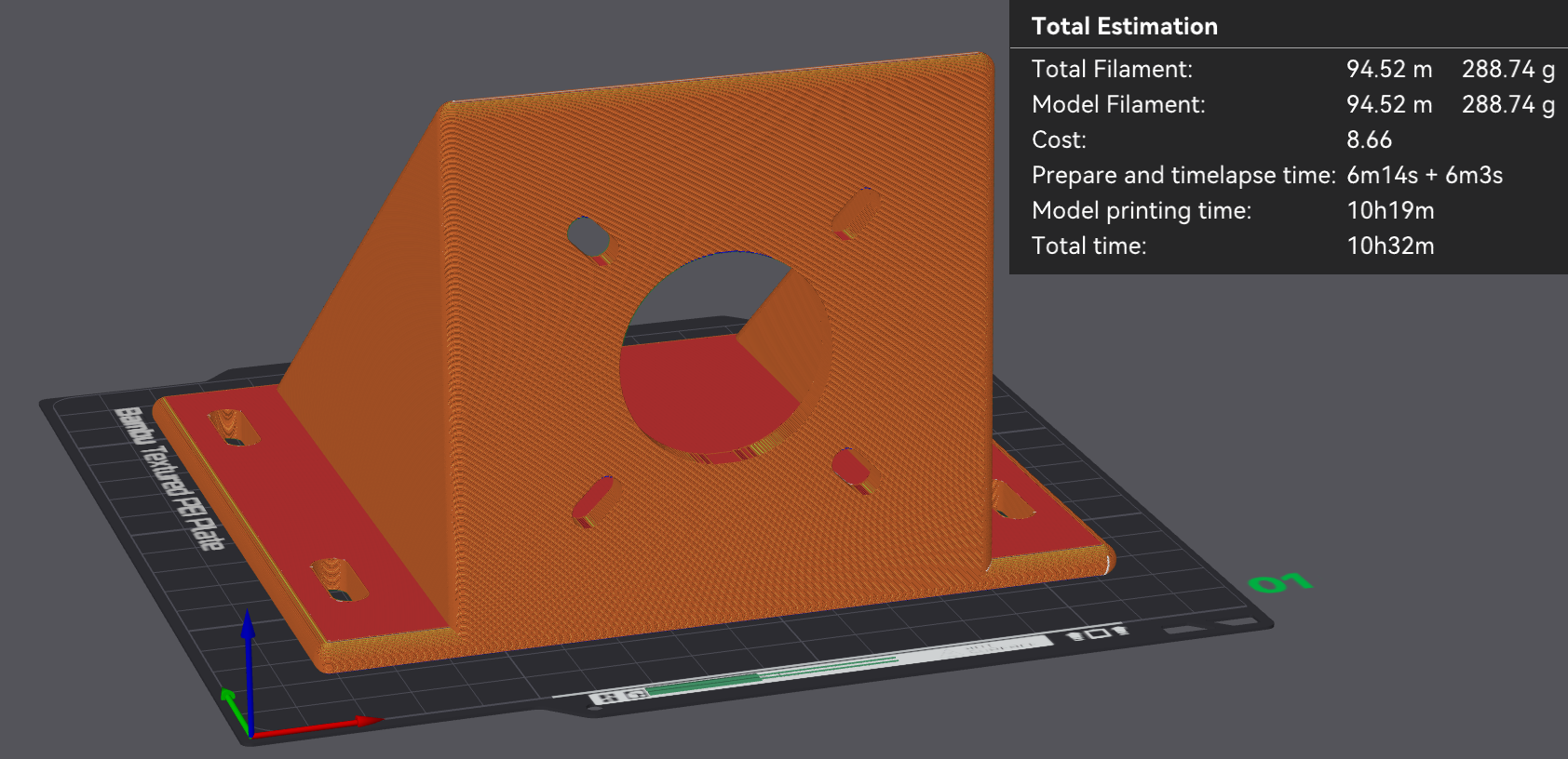
ACT57BLF02 bracket – slicing preview (PLA, 100% infill).
2.1 Step 1: Mount DUT Motor to 3D printed braket, align and fix
As a first step, mount the DUT motor in the mounting bracket that you have 3D printed.
After that, fix the motor bracket to the T-Slot or your base support.
If you are using different motors be sure to make the brackets in such a way that the motor shafts are aligned. This is very important. Align the DUT motor shaft with the dyno motor shaft using the shaft coupler to help you align them.
Fix everything by tightening the different screws. If the shaft coupler spins freely, then the “hand alignment process” was correct, if you see wiggle or that the shaft requires different forces in different positions to rotate, that might mean that the motor shafts are not completely aligned. If that happens please untighten, move the brackets as needed and tighten the screws needed to guarantee the best alignment possible.
DUT Standard Configuration
Tip
The shaft coupler can handle some small misalignment but will add unnecessary force to the Motor shafts, making the control not reliable, for this reason try to ensure shaft alignment between motors.
2.2 Setup Boards and wire them to the motor
2.2.1 Wiring the Device-Under-Test side
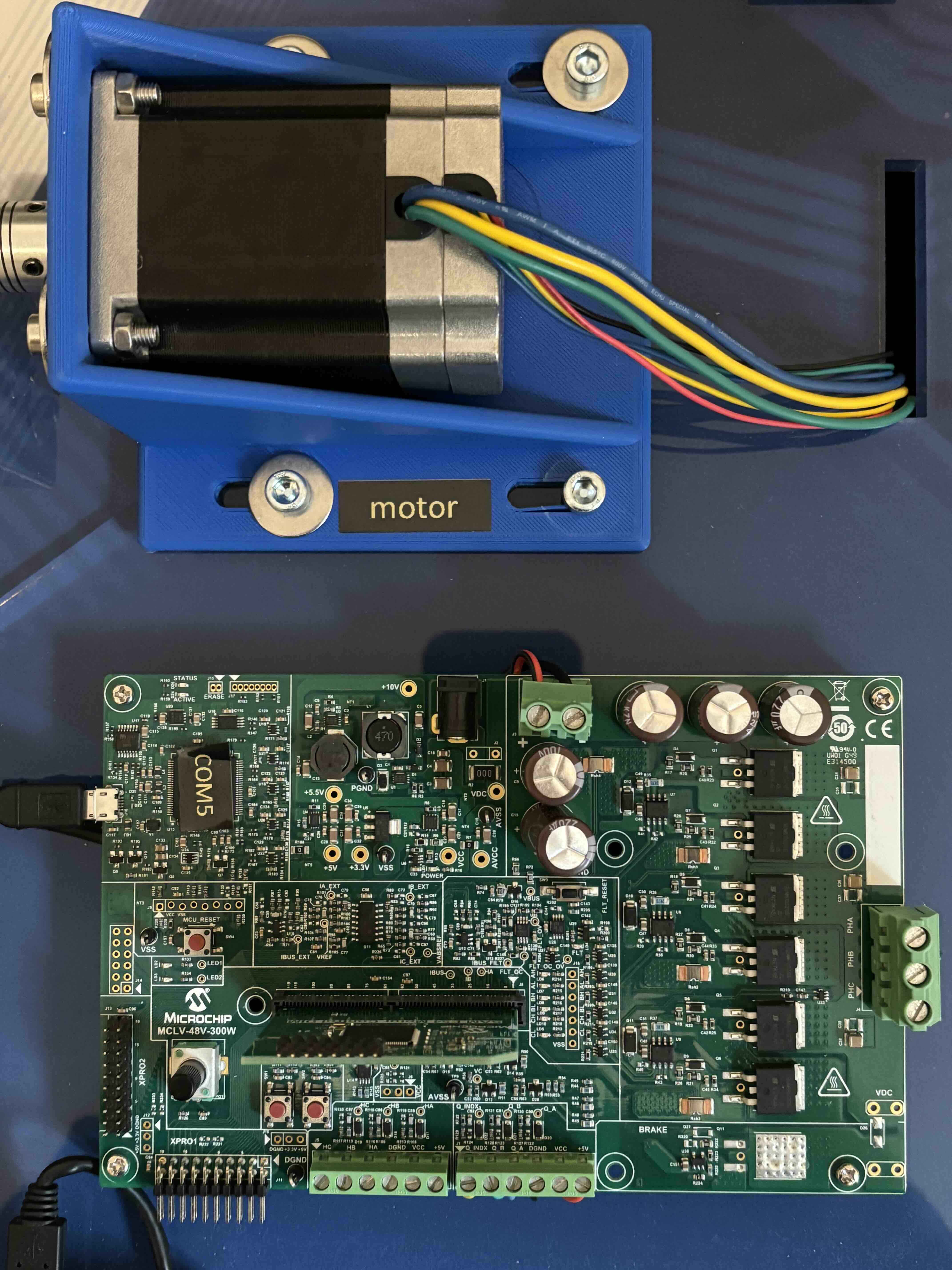
For Wiring the ACT motor to the MCLV-48V-300W board follow the image below as reference.
For phase A connect the yelow wire, for phase B connect the green wire and for phase C connect the BLU wire
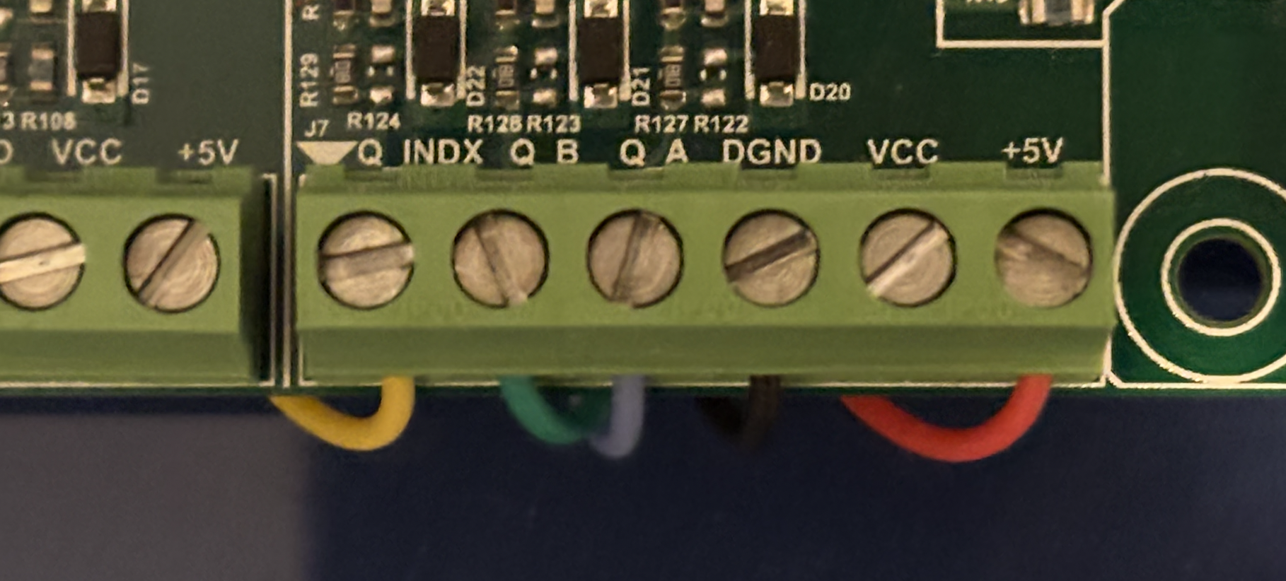
Enocder ACT Motor Wiring to MCLV-48V-300W |
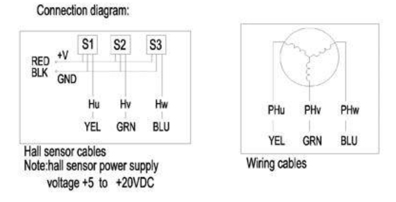
Connection Diagrams |
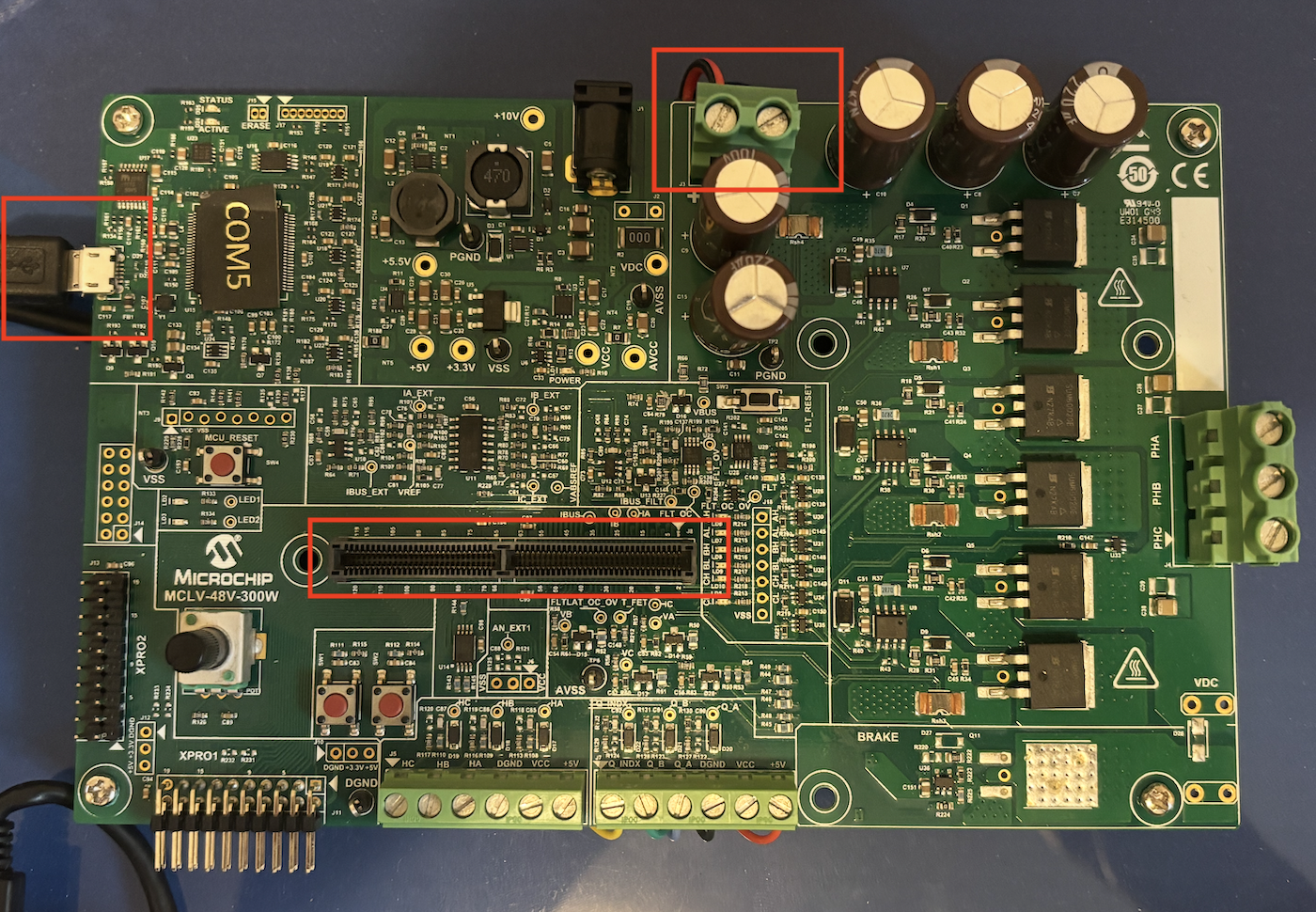
2.2.2 Configure MCLV-48V-300W (DUT)
For the MCLV-48V-300W you should follow the conenction shown below.
Note that this board hosts the DIM for motor-control algorithms. The motor-side HEX downloads are listed below.
Tip
The MCLV48_300_DIMhold.stl is not necessary, but to guarantee better connection of the DIM boards to the MCLV-48V-300W board the suggestion is to 3D print one and use it.
MCLV-48V-300W board configuration
The DUT board shares the DC-link with the dyno board. Follow the warning and wiring notes on Make Your MC-Dyno.
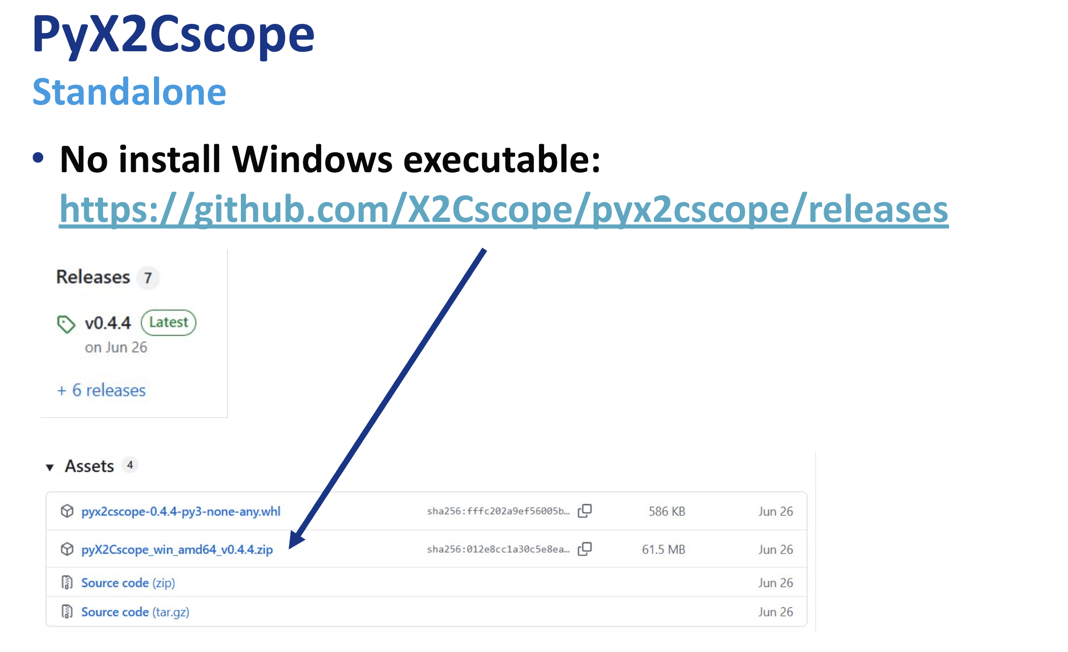
3. Monitor motor behavior with pyX2Cscope
To view motor behavior on the DUT side, you can use pyX2Cscope through Python. There are also standalone apps you can download and run directly without installing anything beyond the app itself. To download the Standalone App this is the up-to-date link: pyX2Cscope releases.
Tip
To actually being able to monitor the board, you will need to load to pyX2Cscope the .elf file related to the project that is loaded to the board. You can find the .elf files in the production dist folder for the project currently loaded on the board. All motor control examples by Microchip are already compatible with X2Cscope, so the only thing you need to do is program the board, and load the .elf file.
Here is a good video showing how to use X2Cscope with some code: Video Tutorial Example using motorBench® Development Suite.
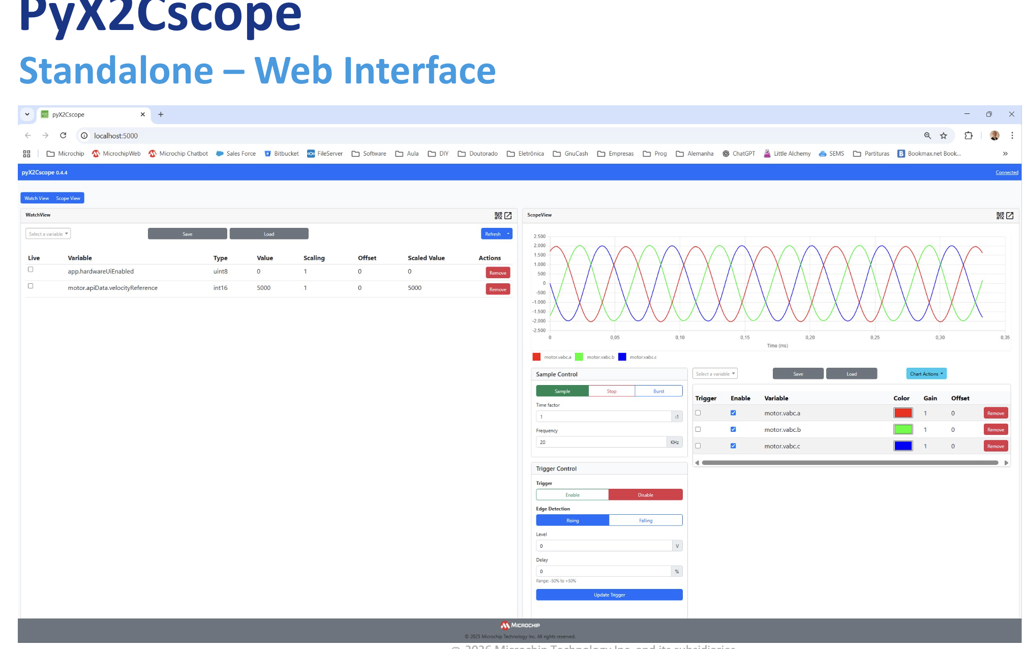
pyX2Cscope Standalone Web Interface |
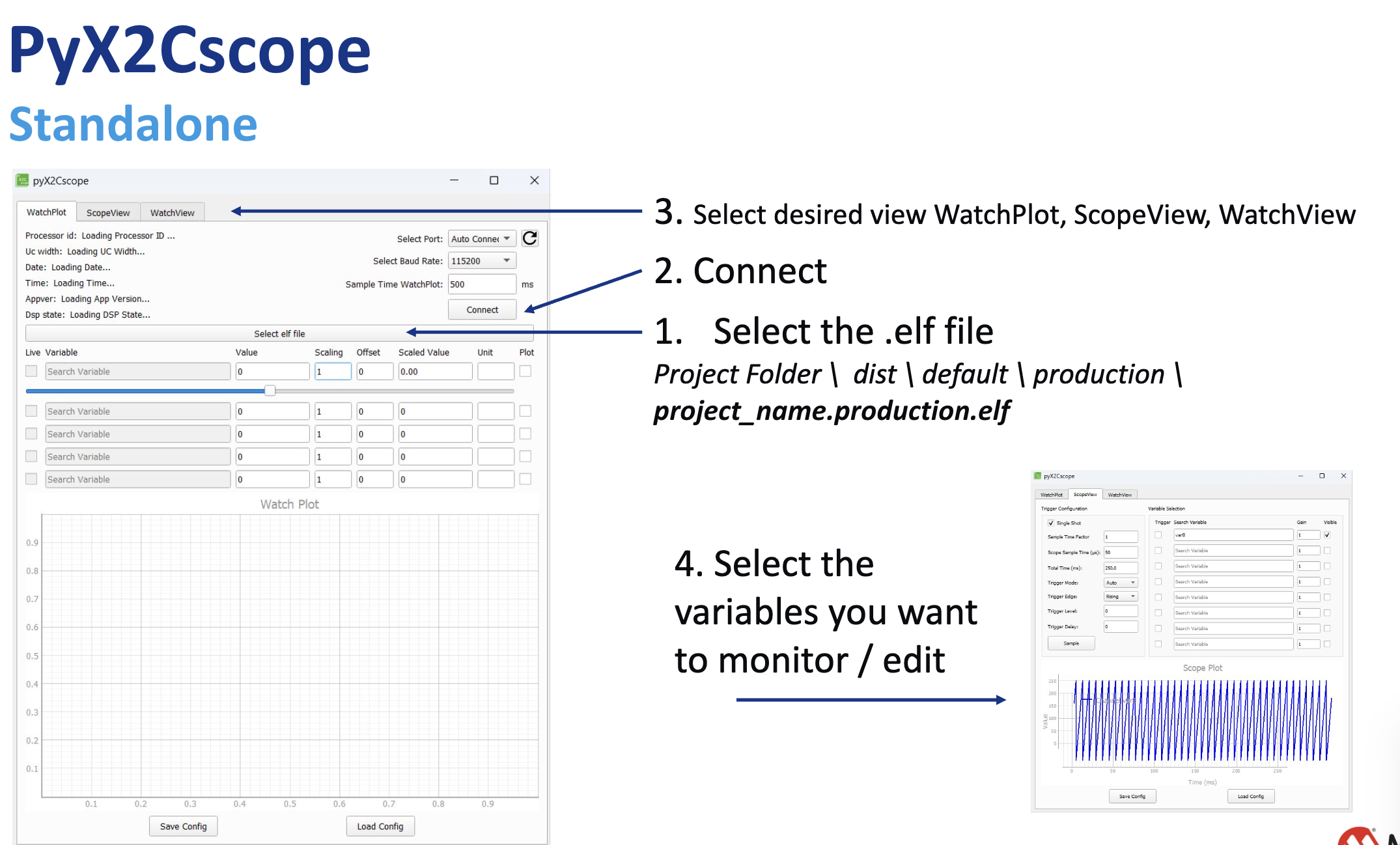
pyX2Cscope Standalone App |
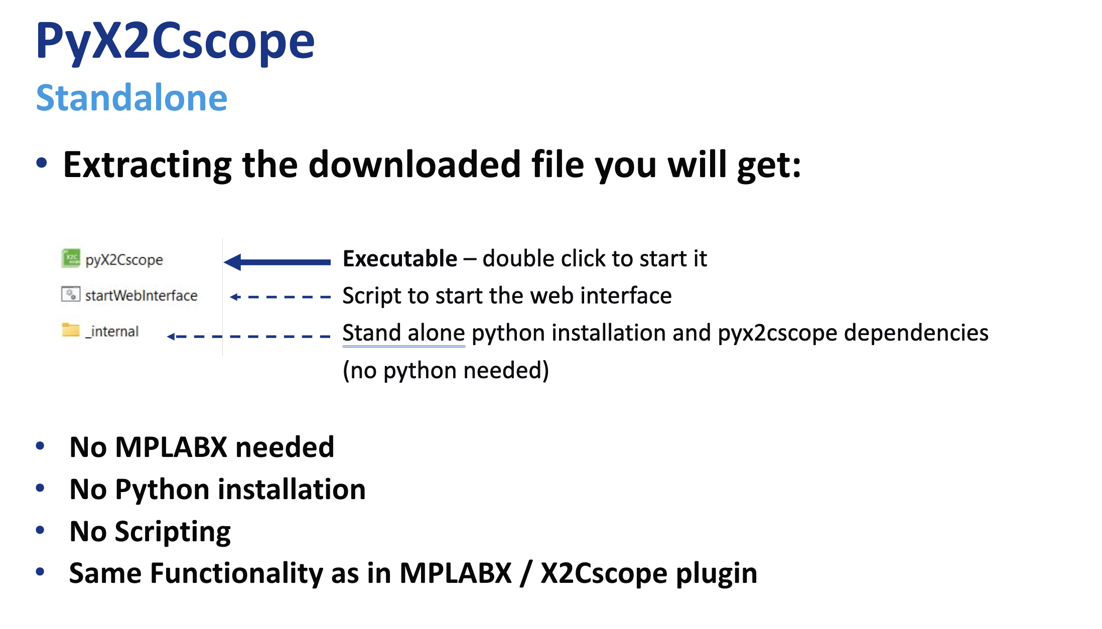
Downloading and using pyX2Cscope Standalone |
Downloading and using pyX2Cscope Standalone (2) |
These HEX files target the motor-side control DIM installed on the MCLV-48V-300W Development Board (EV18H47A). They are used to showcase different motor-control algorithms on the dyno.
Example DIM: dsPIC33CK256MP508 Motor Control DIM (EV62P66A) https://www.microchip.com/en-us/development-tool/ev62p66a
HEX Location
motor_ACT57BLF02/mclv48v300w_dim_hex/doc/standalone/
Downloads
Algorithm Notes
DIM mapping:
Single-shunt demo runs on the dsPIC33AK128MC106 DIM.
ZS/MT and X2C demos run on the dsPIC33CK256MP508 DIM.
Single-shunt current measurement (MCAF R8):
Samples the DC-link current twice in a single PWM period and reconstructs phase currents based on the inverter switching state.
Requires a dedicated, high-priority ADC ISR and a minimum switching-state window (t_sample + dead time).
For estimators other than ZS/MT, use single update in Dual Edge Center Aligned PWM mode.
Zero-Speed / Maximum Torque (ZS/MT) Estimator
ZS/MT is a sensorless position and speed estimation algorithm specifically designed to operate where back-EMF based estimators fail, at zero and ultra-low speeds.
Operating Principle - High-Frequency Signal Injection
Unlike PLL-type estimators, ZS/MT is intrusive: it injects a high-frequency excitation voltage into the stator and measures the motor’s response. This leverages motor saliency to determine rotor angle even at standstill.
Motor Requirements (Saliency)
ZS/MT requires a motor with significant Ld != Lq saliency. It is thus primarily intended for IPMSM machines, where q-axis inductance is notably higher than d-axis inductance.
Startup Sequence - IPC for Zero-Speed Torque Production
To deliver torque from standstill, ZS/MT uses a startup procedure termed “ZS/MT + Initial Position Correction (IPC)”, allowing the controller to correctly align the stator field before any mechanical motion begins.
Hybrid Operation - Low-Speed to High-Speed Transition
Because the injected signal consumes voltage headroom, ZS/MT cannot achieve the absolute maximum speed by itself. In practice, it is combined with a back-EMF estimator (for example, PLL) using a hybrid scheme (for example, “Minotaur hard-switch”) to allow:
ZS/MT for 0-to-low-speed operation
PLL for mid-to-high-speed operation
Tuning and Configuration Parameters
Reference hardware: https://www.microchip.com/en-us/development-tool/ev18h47a